What is this?
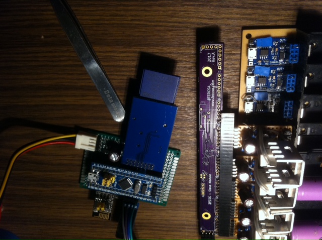
A modular battery tester for 18650s aka FERCSA's Charger and Discharger Station with ThingSpeak support.
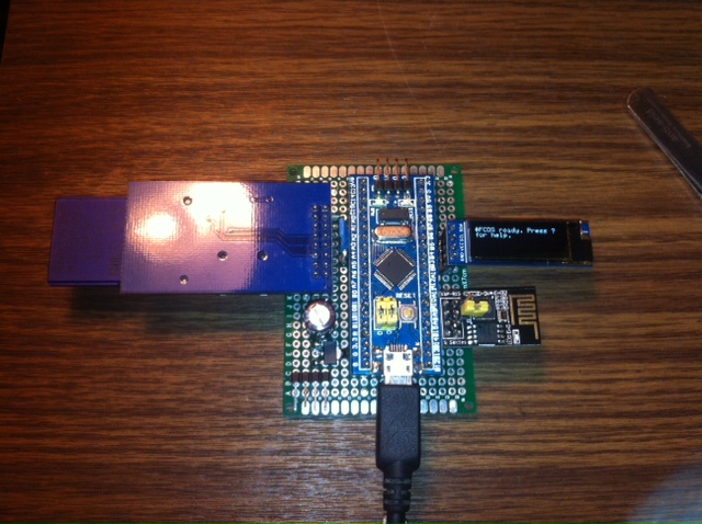


Very simple, everybody can make it on a proto/perf board.
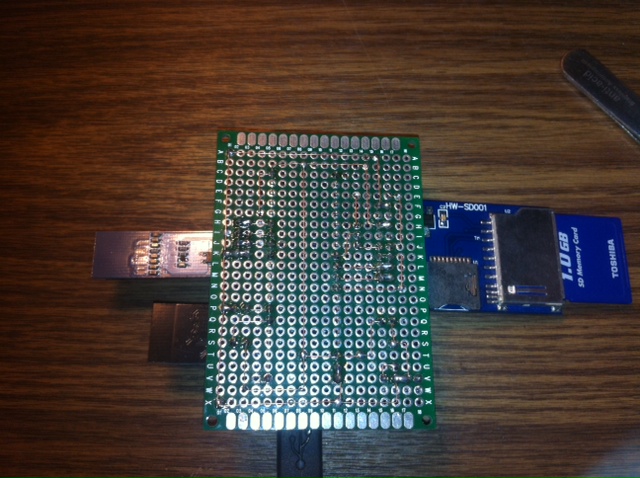
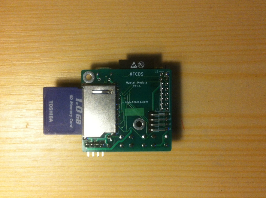
Parts list:Please modify the schematic for your SD Card reader. My reader is a combo reader and it's not obtainable on eBay anymore. A newer variant on the last three picture.
Schematic: Download
./stm32flash /dev/ttyUSB0 -b 230400 -w bootloader.bin -v -S 0x8000000
./stm32flash /dev/ttyUSB0 -b 230400 -w fcds_stm32_beta.bin -v -S 0x8002000
stm32flash COM3 -b 230400 -w bootloader.bin -v -S 0x8000000
stm32flash COM3 -b 230400 -w fcds_stm32_beta.bin -v -S 0x8002000
C:\stm32>stm32flash COM3 -b 230400 -w bootloader.bin -v -S 0x8000000
stm32flash 0.4

http://stm32flash.googlecode.com/

Using Parser : Raw BINARY
Interface serial_w32: 230400 8E1
Version      : 0x22
Option 1     : 0x00
Option 2     : 0x00
Device ID    : 0x0410 (Medium-density)
- RAM        : 20KiB  (512b reserved by bootloader)
- Flash      : 128KiB (sector size: 4x1024)
- Option RAM : 16b
- System RAM : 2KiB
Write to memory
Erasing memory
Wrote and verified address 0x08001c14 (100.00%) Done.


C:\stm32>stm32flash COM3 -b 230400 -w fcds_stm32_beta.bin -v -S 0x8002000
stm32flash 0.4

http://stm32flash.googlecode.com/

Using Parser : Raw BINARY
Interface serial_w32: 230400 8E1
Version      : 0x22
Option 1     : 0x00
Option 2     : 0x00
Device ID    : 0x0410 (Medium-density)
- RAM        : 20KiB  (512b reserved by bootloader)
- Flash      : 128KiB (sector size: 4x1024)
- Option RAM : 16b
- System RAM : 2KiB
Write to memory
Erasing memory
Wrote and verified address 0x08017090 (100.00%) Done.

python "../esptool.py" --port /dev/ttyUSB0 --baud 460800 write_flash \
  --flash_freq 40m --flash_mode dio --flash_size 1MB \
  0x0000 boot_v1.5.bin 0x1000 fcds_esp_user1_beta.bin \
  0xFC000 esp_init_data_default.bin 0xFE000 blank.bin
esptool.py v2.0-beta1
Connecting....
Detecting chip type... ESP8266
Uploading stub...
Running stub...
Stub running...
Changing baud rate to 460800
Changed.
Attaching SPI flash...
Configuring flash size...
Flash params set to 0x0220
Compressed 3232 bytes to 2336...
Wrote 3232 bytes (2336 compressed) at 0x00000000 in 0.1 seconds (effective 472.1 kbit/s)...
Hash of data verified.
Compressed 313364 bytes to 234799...
Wrote 313364 bytes (234799 compressed) at 0x00001000 in 5.9 seconds (effective 423.9 kbit/s)...
Hash of data verified.
Compressed 128 bytes to 77...
Wrote 128 bytes (77 compressed) at 0x000fc000 in 0.0 seconds (effective 302.9 kbit/s)...
Hash of data verified.
Compressed 4096 bytes to 26...
Wrote 4096 bytes (26 compressed) at 0x000fe000 in 0.0 seconds (effective 13528.8 kbit/s)...
Hash of data verified.

Leaving...
Hard resetting...
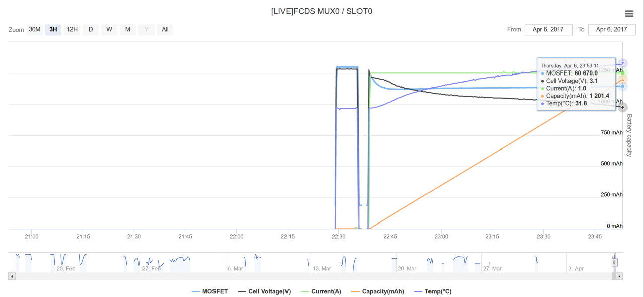
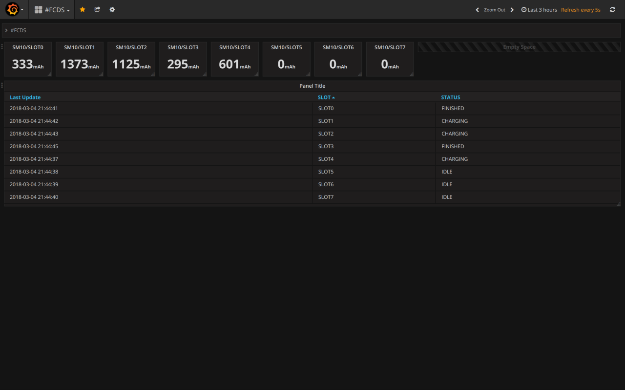
A few sample pictures from the web interface


You can check out a demo here: link. Sample key: SM8 Slot0 id:227746 key:1ELXX5VKXUO61FU4 or just use your own.
A few sample log from telnet
........
#Welcome FERCSA!
#[SDCARD]: Initialized.
#[WIFI]: Initialization failed!
#[WIFI]: Can't set time!
#[I2C]: Scanning I2C address..
........
#[I2C]: Found SM8 on I2C address 0x8
.
#[I2C]: Found SM9 on I2C address 0x9
.......
#[I2C]: SM8 initialized at 0x8
#[I2C]: SM9 initialized at 0x9
#[I2C]: All channel set to default!
#[SM]: All dividers loaded from internal memory! Don't forget to calibrate!
#[SM]: All ThingSpeak API key loaded from internal memory!
#FCDS ready. Press ? for help.
Currently selected:     SM8 / SLOT0                              www.fercsa.com #FERCSA
+---------+---------+---------+---------+---------+---------+---------+---------+---------+
| q=Slot0 | w=Slot1 | e=Slot2 | r=Slot3 | t=Slot4 | z=Slot5 | u=Slot6 | i=Slot7 | a=SM    |
| 0=Stop  | 1=Reset | 2=Charg | 3=Disch | 4=Int.R | 5=Stat  | 6=Calib | 7=Logs  | ?=HELP  |
+---------+---------+---------+---------+---------+---------+---------+---------+---------+
#Slave module and slot selector
 Press q for select slot 0.
 Press w for select slot 1.
 Press e for select slot 2.
 Press r for select slot 3.
 Press t for select slot 4.
 Press z for select slot 5.
 Press u for select slot 6.
 Press i for select slot 7.
 Press a for select slave module.
#Menu
 Press 0 for stop.
 Press 1 for stop and reset.
 Press 2 for start charging.
 Press 3 for start discharging.
 Press 4 for measure internal DC resistance. (Based on IEC 61960)
 Press 5 for status.
 Press 6 for calibration. (Connect Vref3V3 to battery positive pin)
 Press 7 for logfile.
 Press s for automatic discharge.
 Press d for set your ThingSpeak API key for a SM's slot.
 Press f for list all ThingSpeak API keys.
 Press g for set cut off voltage.
 Press h for set discharge current.
 Press j for erase internal memory.
 Press l for initialize the wifi.
 Press m for initialize a selected SM.
 Press n for reset I2C address back to default for a SM.
 Press b for set I2C address for a SM.
 Press v for scan I2C addresses of SMs.
 Press c for list all dividers.
 Press x for list all initialized SM.
 Press 9 for slave module test.
#[SDCARD]: SM8 / SLOT0 Log saved to SD Card.
#[WIFI]: SM8 / SLOT0 Log sent to ThingSpeak.
#Stop.
#[I2C]: Restriction: Should be above 0x08(8) and under 0x77(119). Default: 0x08(8)
#[I2C]: Please respect the I2C specification when you select an address for the Slave Module
#[I2C]: Collision may be happen when you connect more than one at the first time. Don't do that!
#[I2C]: Type a new I2C address for the selected Slave Module: (Example 0x0C in decimal: Type 12 then press ENTER)
13
#[I2C]: New I2C address is set. New address: 0xD
#[I2C]: Scanning I2C address..
.........
#[I2C]: Found SM9 on I2C address 0x9
....
#[I2C]: Found SM13 on I2C address 0xD
...
#[I2C]: SM9 initialized at 0x9
#[I2C]: SM13 initialized at 0xD
#[I2C]: All channel set to default!
#[SM]: All dividers loaded from internal memory! Don't forget to calibrate!
#[SM]: All ThingSpeak API key loaded from internal memory!
#[SDCARD]: SM9 / SLOT0 Log saved to SD Card.
#[WIFI]: SM9 / SLOT0 Log sent to ThingSpeak.
#Stop.
"2017-12-18 13:44:51",8,0,58680,3.71,0.28,0.21,25.86
"2017-12-18 13:45:01",8,0,58251,3.54,1.04,2.86,26.12
"2017-12-18 13:45:11",8,0,57951,3.51,1.04,5.21,25.53
"2017-12-18 13:45:21",8,0,57671,3.55,1.04,10.32,25.15
"2017-12-18 13:45:31",8,0,57407,3.55,1.03,13.18,25.19
"2017-12-18 17:36:11",8,0,20000,0.00,0.00,0.00,0.00
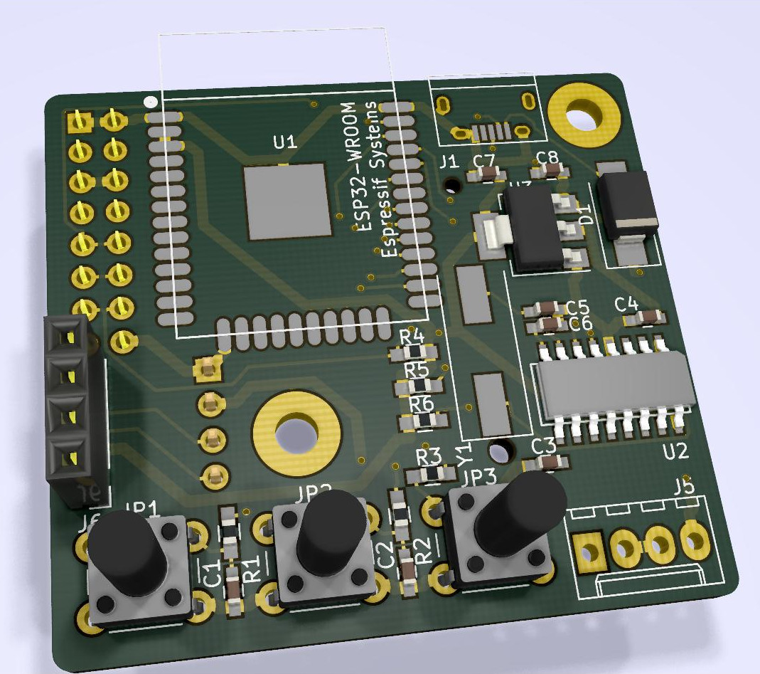
Later there will be a ESP32 port for a more simple, more powerful master module but in the current stage with lack of ... blah-blah The ESP32 port is ready!! Later I'll publish the schematic for it, but if you're impatient drop me an email.
Also if you starting your build these days I advise you to choose the ESP32 version (DevKitC or ESP-WROOM32). Currently I'm designing a new master module around the ESP32-WROOM32, it will be a factory made PCB and includes all necessary passive components like buttons, sd card reader and etc. If you can't wait just go with the DevKitC.
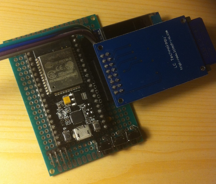
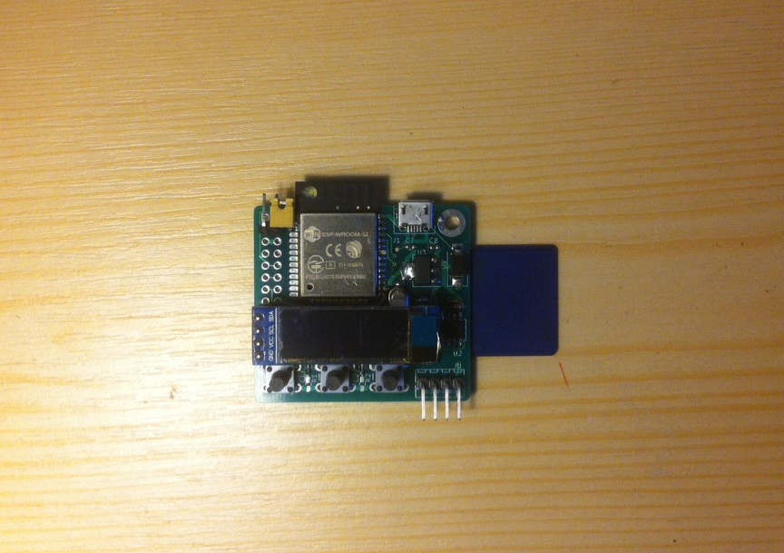
Very simple, everybody can make it on a proto/perf board. Easier than the STM32.
Parts list for the DIY version:ESP32 version includes a Telnet server and OTA update for new firmware too!
Please modify the schematic for your SD Card reader, it can be different.
Schematic: Download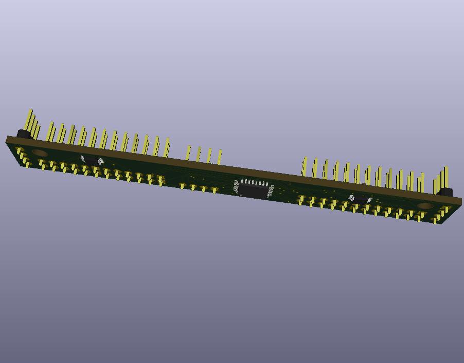


Because various reason, mostly cost I made a board with a cheap custom programmable logic chip. Communication interface: I2C.
Default address: 0x08(8). There is no address limitation! Add these boards one at a time then change the address in telnet console.
I advise 0x09(9) and up, because if you got a new one it's gonna be 0x08(8) by default, easier to config. Another tip: label your boards.
One Slave Module can handle 8 battery. Maximum daisy-chanable modules: 112 with respect of the I2C specification, otherwise all 7-bit usable which is equal to 128.
Contact me if you need one.
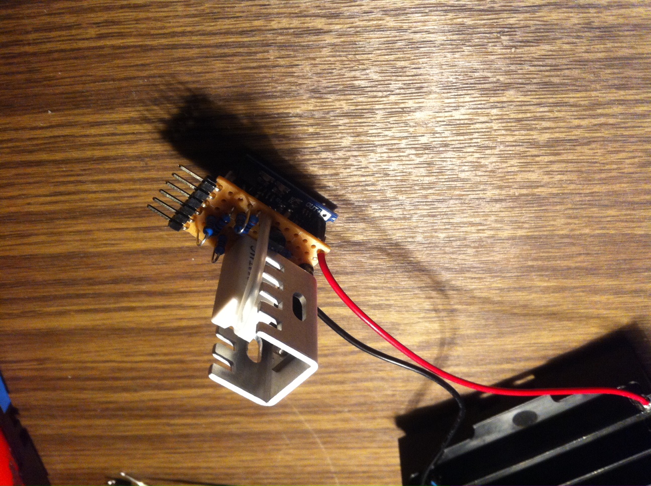
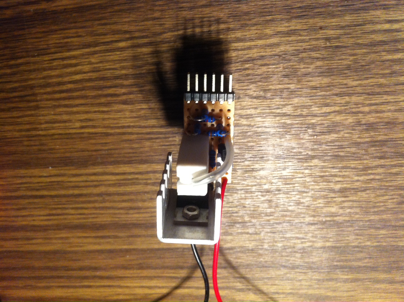


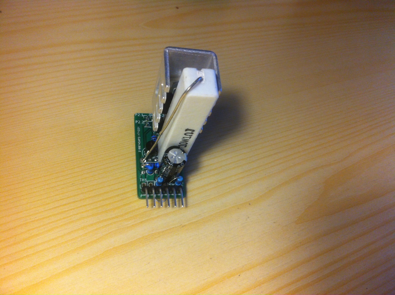
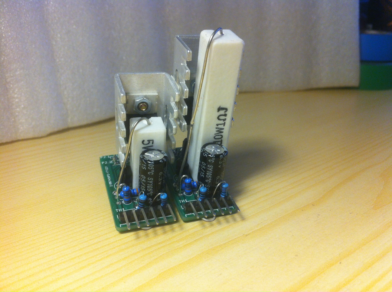
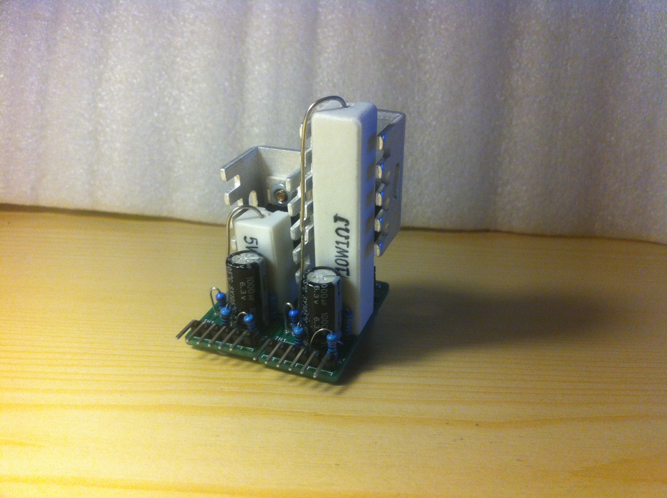
Simple, DIYable, everybody can make it on a proto/perf board, but after a ten or twenty module you're gonna be call your jesus.
To speed things up I made a few factory made PCBs, contact me if you need some. Another advantage is you don't need jumpwires for the temp sensor(TH1).
Also you can change the power resistor from 5W to 10W then the module can handle 2.5A discharge current easily. Otherwise 1.25A top. These values are without any airflow!
You can set your discharge current in telnet console as you wish.
Schematic and PCB: Download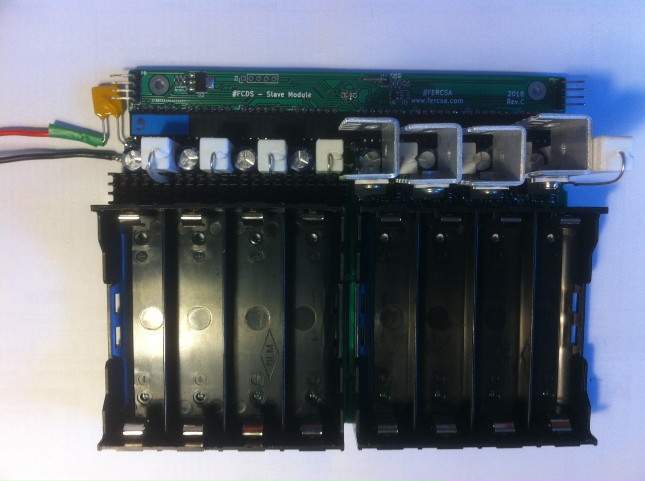
I designed a new PCB for this, because a lot of TP4056 modules out there with clone chips and this multi module includes all the necessary components for charging and discharging 8 cells at once.
Just connect your Slave Module then it's ready to go.


Currently I have two design for it. One with a big proto board and one cheaper solution.
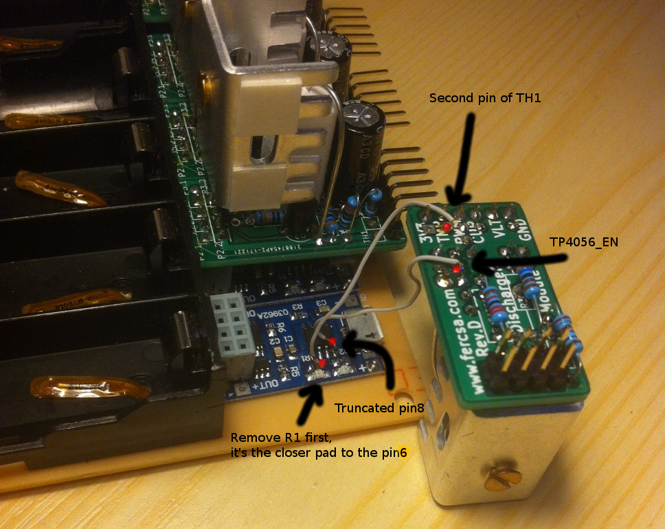
Exploiting the TP4056 Charger's enable pin: Cut pin number 8 with a side cutter then solder a wire to the truncated leg. After that connect the wire other end to the Discharger Module's P4(TP4056_EN). See the 5th picture of the previous section above.
Since I adopted to my firmware, we can detect when a cell is charged. What you need to do is simple: Remove R1 on the TP4056 charger then connect a wire from one of the pad of R1 (which is closer to pin6) to the second pin of TH1 on the Discharger Module.
There is a Grafana plugin also, just change the FCDS console output to CSV.
Then start my python script on your Raspberry or any linux box. It's act as a bridge and use influxDB as database.
More info on the forum and in my script's comment section. This plugin is a very basic example, but you can tweak it as you wish.
Grafana Python script: DownloadFirst video is outdated, the design is changed and I added a lot more feature. More videos coming.. not my strong suit honestly. Check back later.
All pictures here are clickable.
#FERCSA